
Release notes IDEA StatiCa 23.0
News for Steel
Speed, precision, and clarity are the order of the day for our Steel applications in IDEA StatiCa 23.0. For those of you looking for more transparency in your code check outputs, we have included more features and improvements to reports. As one example, not only can you see things such as eccentricities added due to the alignment of one plate to another, you can also see the load effects, whether they start at the beginning of the member or at the end. Plus, should you, in your excitement, accidently click the report tab, the report will not auto-generate, which is guaranteed to avoid some serious frustration!
Did we mention AISC prequalification checks for seismic design? This allows you to already see limits in the 3D scene, remedy any problems in your models immediately with everything then clearly shown in check tables and the report.
With our stunning new mesher, you get even more accurate results with improved reliability and a nicer mesh. Now open sections have a finer mesh by default, helping you achieve results that are safer than ever before.
Code check more with transparent inputs
Check welds of welded sections

You can change the type of the weld from butt to fillet weld and set its parameters as material or weld throat thickness.
The option to change the weld type to such weld profiles to perform crane girder welds and crane runway beam welds is available for welded cross-sections in the library:

The new fields with the weld parameters can be found in the cross-section definition window:

If you want to review the parameters, you can open the appropriate cross-section in Materials:

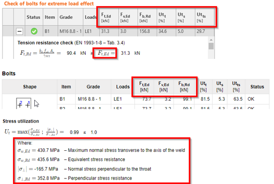
The welds are checked, and the values of stress, strain, and checks based on code are presented in the Results:

All the results are presented also in the Report.

This feature is available in IDEA StatiCa Connection, Member, and Checkbot. In Connection, the full functionality is provided. For projects in Member, the welds of the welded cross-sections can be defined, nevertheless, the code-checks of the full member's welds are not present. The welded cross-sections can be defined in Checkbot as well.
Available in the Enhanced edition of IDEA StatiCa Steel.
Scarica la nuova versione di IDEA StatiCa e prova tutte le funzionalità
Detailed model and loads reporting
You are able to generate a more detailed report with the following information:
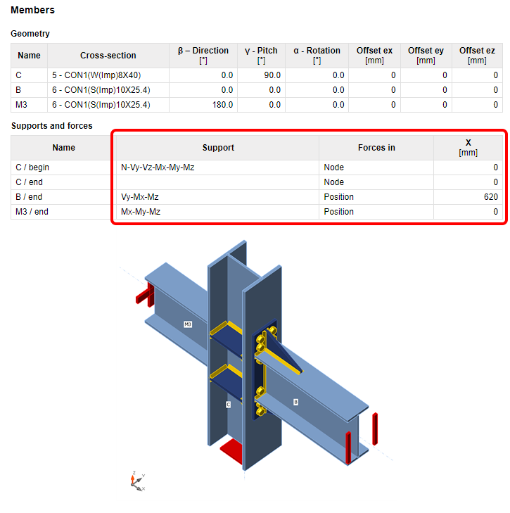
Supports and forces
The chosen model type (the applied supports, respectively) are presented in the table and in the figure below. For example, the supported end of the bearing member will have all six reactions listed, while the free end will have none of them. For the N-Vy-Vz model type, the complementary forces, i.e., Mx-My-Mz, will be presented. The calculation report also includes boundary conditions.
The table also presents the position of the applied forces.
Alignment added to eccentricities
The chosen alignment type is now taken into account when displaying the table of members' offsets. The geometry table in the report calculates the total offset in the global coordinates.

Load effects
The loaded part of members (Begin/End), as well as the table of unbalanced forces, has been added to the table of applied load effects.

Buckling shape
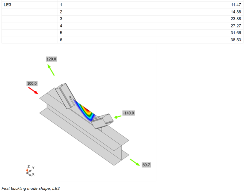
A figure with the most probable buckling shape (lowest factor) has been added to the report for when the buckling analysis is performed.
Report not generated automatically
Generating the report may take some time, and it is not always needed. From now on, the report is generated manually by pressing the Generate button.

Currently, this functionality works properly just the first time the Report tab is opened. The next time, the report is automatically regenerated. This may be a part of future development.
Available in both Expert and Enhanced editions of IDEA StatiCa Steel.
Download the new version of IDEA StatiCa and try all the features
Qualification checks of seismic prequalified connections for AISC
The results of the checks are listed in a new table in the report with all the necessary information to prove that the requirements of prequalified connections design of the code ANSI/AISC 358-16 have been fulfilled.
The checking of the code requirements is done in real-time. Short messages displayed directly on the 3D scene help the designer create the connection design in a more efficient way with significant time savings.
This new feature is intended as a check of scope of prequalification for all engineers who perform structure designs and analysis of structures according to the AISC codes for seismic design.
Theoretical background
Standard ANSI/AISC 358-16 specifies the design, detailing, fabrication and quality criteria for connections that are prequalified in accordance with the AISC Seismic Provisions for Structural Steel Buildings (herein referred to as AISC Seismic Provisions) for use with special moment frames (SMF) and intermediate moment frames (IMF). The connections contained in this standard are prequalified to meet the requirements in AISC Seismic Provisions only when designed and constructed in accordance with the requirements of this standard.
First setting
There is a new property grid where it is necessary to set the Analysis type to Capacity design and enable the option for Prequalified connection.

After that, it is possible to select the System and Connection type according to the one in code ANSI/AISC 358-16. There are two possible systems, Special moment frame (SMF) and Intermediate moment frame (IMF)
The connection types incorporated into the Connection app were selected based on their frequency of use and usability for analysis in the Connection app. A list of them is shown in the figure below.


Models for seismic design are proposed in the wizard. The user can choose a single-sided or double-sided beam connected to the column. All these models are set to the proper connection type by default and are set up with appropriate load effects.

Usage
A message regarding the design of the prequalified connection is always displayed to the user.
If the design of the prequalified connection meets the code requirements, a green-OK-status message is displayed.
If any of the requirements is not fulfilled, the status of the message is changed to a yellow-exclamation-mark warning and a short message with the specific limitation is displayed. This message provides an immediate response to the designer's action as well as a specific value that needs attention for correction.
Most of the checked values are related to IDEA StatiCa operations. If the design consists of only basic items such as stiffening plate, bolt grip, etc., a generic message can appear directing the user to use IDEA StatiCa's operations instead.

The results of the successful analysis of the detail are presented in the Report. There is a new table where all provided checks are stated. Every check has information about the item, the current value and requested value limit, a reference to the chapter of the code and the status of the check.
The used system and Connection type are also stated.

Specification of the checked requirements
Connection type specific checks and the general checks that are not related to a specific connection type are provided.
General checks
A check of Limiting Width-to-Thickness Ratios is performed according to AISC 341-16: Chapter D.1.1b and Table D1.1. The minimum requested slenderness of the flange and the web of the cross-section is checked.
A check of Type of member’s section according to the ANSI/AISC 358-16: Chapter 2.3 is performed. The types of the cross-section used in the members for prequalified design are limited according to the code. In the Connection app, the limitations of the supported cross sections are used for prequalified connection design.
Types of cross-sections used for beams:

Types of cross-sections usable for columns:

Fastening assemblies are checked according to ANSI/AISC 358-16: Chapter 4.1. There is a list of bolt assemblies dedicated to a prequalified connection.
Protected zones are checked according to ANSI/AISC 341-16: Chapter D1.3.
The geometry of the Continuity plates is checked according to AISC 341-16: Chapter E2.6f.2 and Chapter E3.6f.2.
The geometry of the Doubler plates is checked according to AISC 341-16: Chapter E3.6e.
Specific checks
Reduced Beam Section (RBS)

This Connection type is checked according to Chapter 5 in code ANSI/AISC 358-16. The following checks are provided:
- Checks of the beam limitations according to Chapter 5.3.1.
- Checks of the column limitations according to Chapter 5.3.2.
- Checks of the beam-flange to column weld limitations according to Chapter 5.5 and a related check of the weld access hole according to AISC 360-16: Chapter J1.6.
- A check of the beam-web to column weld limitations according to Chapter 5.6.
- A check of the geometry of the RBS according to Chapter 5.8 Step 1.
The shear strength according to Chapter 5.6 (1) and the weld of the fin plate, according to Chapter 5.6 (2), are stated as out of scope of the check in Connection.
A new feature is prepared for the pre-design of the weld access hole, which is performed in the beam web according to the AISC Seismic Design Manual – Table 1-1. This feature can be used to define the optimal geometry of the weld access hole by software that fulfills the code's requirements.

Bolted Unstiffened/Stiffened Extended End Plate (BUEEP – 4E / BSEEP – 4ES / BSEEP – 8ES)

This connection type is checked according to Chapter 6 in code ANSI/AISC 358-16. The following checks are provided:
- Checks of the beam limitations according to Chapter 6.3.1.
- Checks of the column limitations according to Chapter 6.3.2.
- Checks of the connection detailing limitations according to Chapter 6.7 and Table 6.1. This check contains a check of the bolt and end plate geometry, if stiffened, also the stiffener of the end plate.
The finger shims are not supported in the operation and are stated as out of scope of the check in Connection. Also, the check of the welds for the full strength of the beam web in tension, according to the Chapter 6.7.6 (3), is stated as out of scope of the check in Connection.
Bolted Flange Plate (BFP)

This connection type is checked according to Chapter 7 in code ANSI/AISC 358-16. The following checks are provided:
- Checks of the beam limitations according to Chapter 7.3.1.
- Checks of the column limitations according to Chapter 7.3.2.
- Checks of the connection detailing limitations according to Chapter 7.5. This check contains a check of the plate's material, welds and bolt grade and diameter.

Welded Unreinforced Flange-welded Web
This connection type is checked according to Chapter 8 in code ANSI/AISC 358-16. The following checks are provided:
- Checks of the beam limitations according to Chapter 8.3.1.
- Checks of the column limitations according to Chapter 8.3.2.
- Checks of the beam-flange to column weld limitations according to Chapter 8.5. and a related check of the weld access hole according to AWS D1.8/D1.8M: Chapter 6.11.1.2.
- Check of the beam-web to column weld limitations according to Chapter 8.6.
The weld of the single plate to the column according to the Chapter 5.6 (2) is stated as out of scope of the check in Connection.
A new feature is for the pre-designing of the weld access hole, which is performed in the beam web according to AWS D1.8/D1.8M: Chapter 6.11.1.2. This feature can be used to define the optimal geometry of the weld access hole using the software, which fulfills the code requirements.

Double-tee

This connection type is checked according to Chapter 13 in code ANSI/AISC 358-16. The following checks are provided:
- Checks of the beam limitations according to Chapter 13.3.1.
- Checks of the column limitations according to Chapter 13.3.2.
- Checks of the connection detailing limitations according to Chapter 13.5. This check contains a check of the continuity plates', welds' and bolts' geometry and grade.
Available in Enhanced edition of IDEA StatiCa Steel.
Download the new version of IDEA StatiCa and try all the features
Update of ANSI/AISC 360-22, CSA S16:19 standards, and Taiwan sections
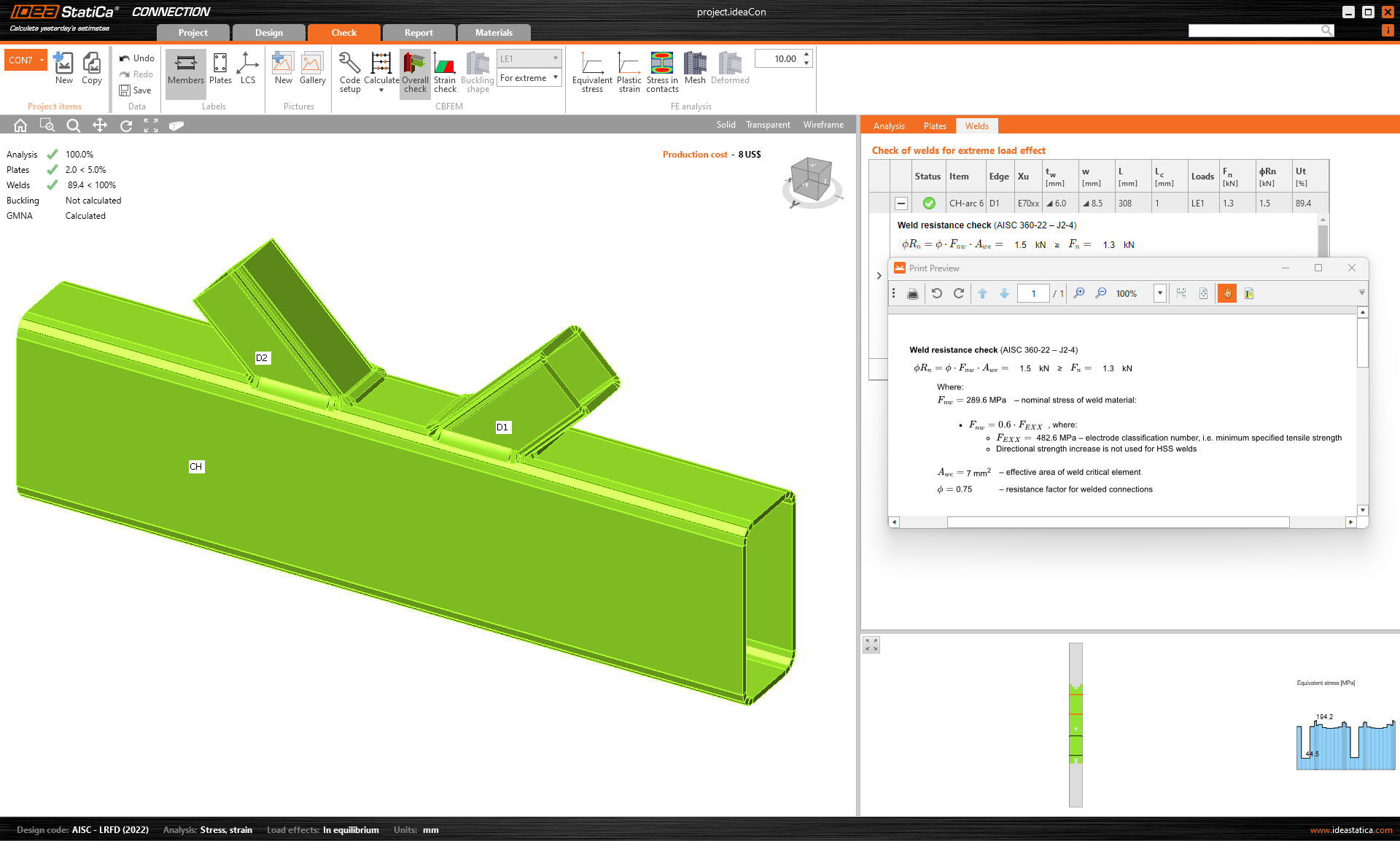
No directional strength increase for HSS (AISC)
For the welds of the rectangular hollow sections, we have implemented the requirement given by the Specification Edition 2022 of AISC. No directional strength increase is assumed in the weld resistance check.
This will lead to better safety of the design.
New codes
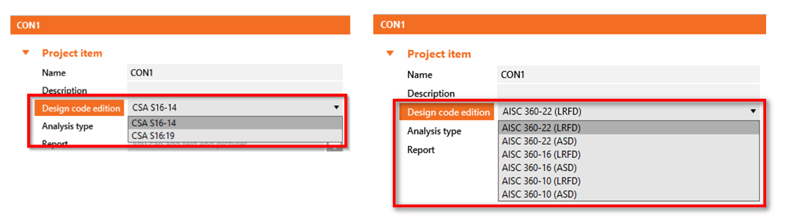
American users may now select the new editions of the design standards:
- CSA S16:19 (Canada, 2022)
- ANSI/AISC 360-22 (USA, 2022)
The steel material database was updated with the new release of AISC 360-22 (in patch 23.0.4).
Cross-section library update
The library of cross-sections (MPRL) was enhanced by local sections from Taiwan. These are:
- Channel parallel
- Channel tapered
- Wide flat plate
The update has been available in Connection, Member, and Checkbot since patch 22.1.1.
Available in the Expert and Enhanced editions of IDEA StatiCa Steel.
Download the new version of IDEA StatiCa and try all the features
Calculation of anchors with stand-off
An anchor with stand-off is designed as a bar element loaded by compressive or tensile force, shear force, and bending moment. The calculation of the bending moment has been improved to respect better the real behavior of stand-off anchors.
The value of the bending moment depends on the ratio between base plate stiffness and anchor stiffness. For a very weak plate and stiff anchors, the bending moment in the anchor will be as follows:

For stiff plate and weak anchors, the bending moment will look like this:
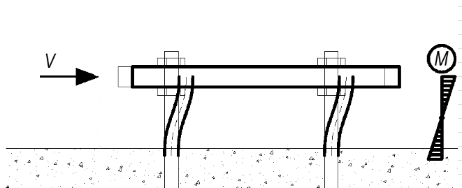
In previous versions, the bending moment in stand-off anchoring was always calculated as in the first case, assuming a weak plate and stiff anchors. The lever arm for moment calculation was the distance between the mid-plane of the plate and the concrete plus one-half of the anchor diameter. This was quite an over-conservative approach.
Since release 22.1.5, the calculation of the bending moment has been updated. The value is determined directly by the finite element model. The anchor is modelled as a beam element and moments in it respect the actual stiffness of the system. The anchor is fixed on both sides, one side is 0.5×d below the concrete level, and the other side is in the mid-plane of the plate. The extreme of the calculated moment is taken into account in the code check then.
More information regarding the code checking of anchors can be found in the theoretical background. Individual codes can be found here: EC, AISC, AS, STO.
Available in both Expert and Enhanced editions of IDEA StatiCa Steel.
Download the new version of IDEA StatiCa and try all the features
Eurocode updates to thin-walled members and anchors
Eurocode refactoring
To comply with the structure of the application, additional slight changes in the code calculations are present in the following:
- Improved formulas in Eurocode
- Improved Check tables with unified subscripts, and units format
- Improved Report tables
This EC refactoring is in both Expert and Enhanced editions of IDEA StatiCa Steel.
Range of EC validity
To increase the perceived safety of use, we have added information about the limitation and validity of the checks. These warnings are displayed at the top of the 3D scene.
Thin-walled members
The warning will tell you when the model stays out of the presumptions given by the Eurocode. This is to improve the safety of the use of application for thin-walled members.
Available in Connection since patch 22.1.5.
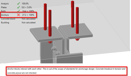
Anchor checks
The warning will show information about why anchors are failing. Anchor design codes are severely limited, and often we cannot perform anchor checks. Information about the limitation is given on top of the formulas.
Available in Connection since patch 22.1.1.
Available in both Expert and Enhanced editions of IDEA StatiCa Steel.
Download the new version of IDEA StatiCa and try all the features
Intuitive and fast modeling
Working plane reference in LCS
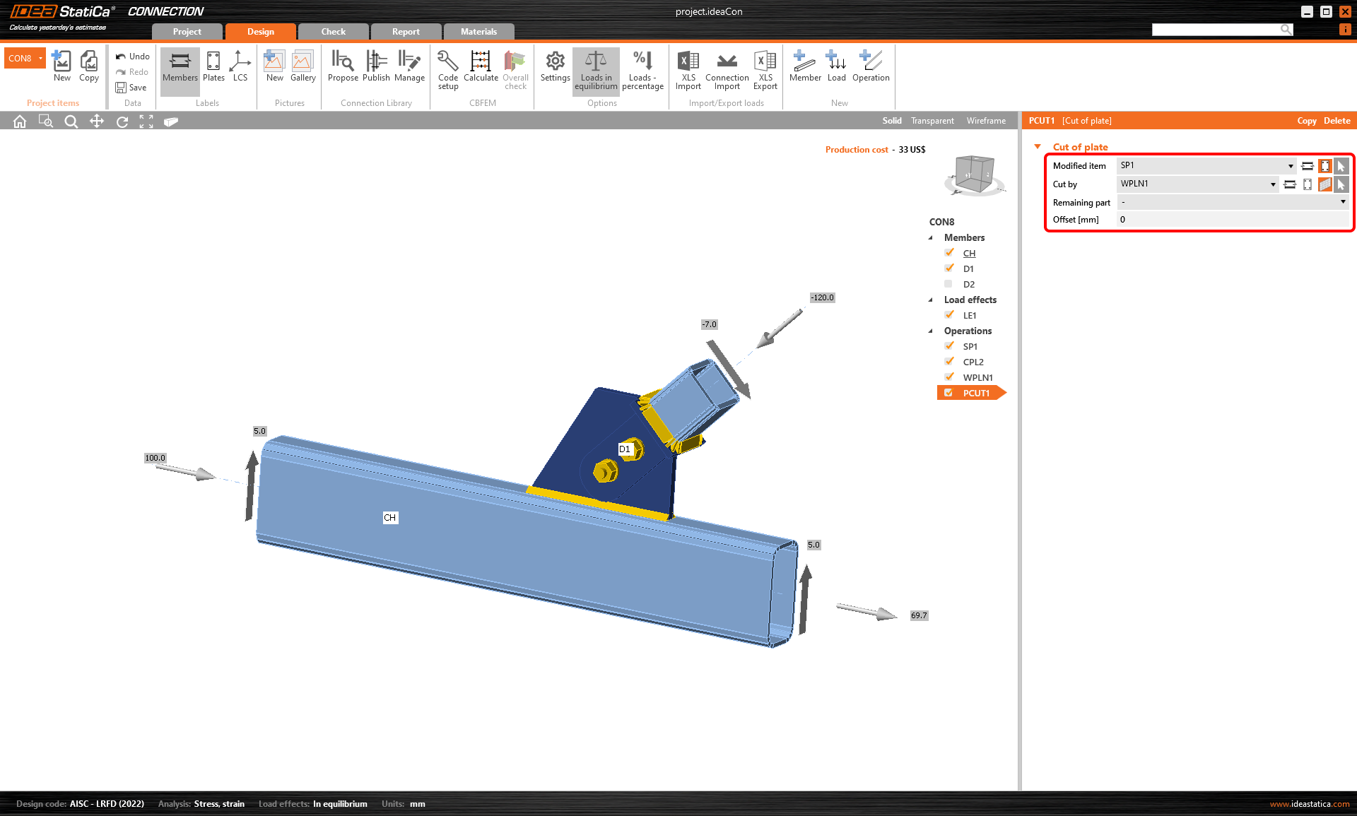
In the past, defining the position and rotation of the working plane could be a little bit difficult. From now on, the origin of Working plane operation may be selected at the Member or Plate local coordinate system.


That is especially useful for, e.g., cuts of gusset plates according to members and all general cuts in the plane of model item.
Available in both Expert and Enhanced editions of IDEA StatiCa Steel.
Download the new version of IDEA StatiCa and try all the features
Changes in the tree of entities
Project settings
For each project, you can set the project name, description, analysis type and also the field with a detailed description to be presented in the report. For the capacity design under AISC, additional parameters are also set here.

Groups of the manufacturing operations
You are able to group the used manufacturing operations based on:
- Operation type
- Connected member
The function can be accessed using by right-mouse clicking Operations. There are three types of view.
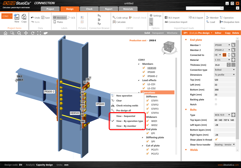
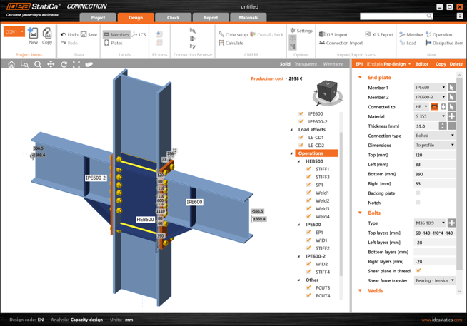
The default (Sequential) refers to the original way of organization of the tree – the order is identical to the order of the addition of each operation.
Please note that the grouping of operations does not change the principle of the application – the operations are always organized by order of appearance.
Available in both Expert and Enhanced editions of IDEA StatiCa Steel.
Download the new version of IDEA StatiCa and try all the features
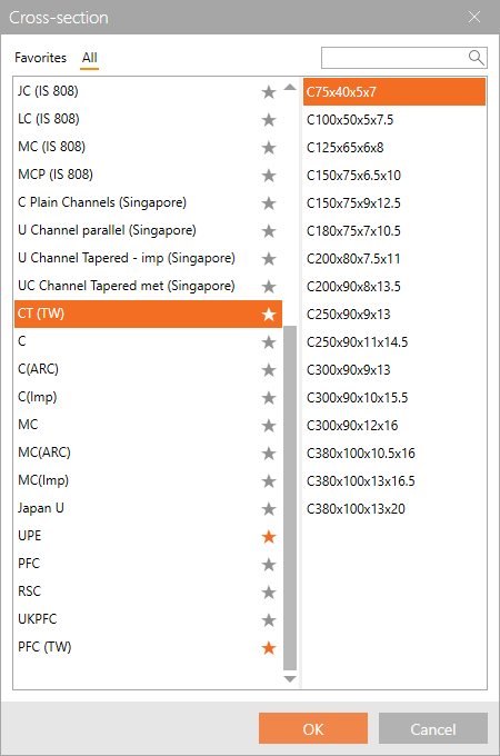
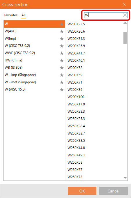
Cross-section searchbox
Since previous versions, you can set the specific class of cross-sections as favorite.
Now, you can use the search box within the library to find the desired section fast and easily. The search always works under the selected tab, i.e., if you are in Favorites, the search will go through your favorite sections only.
Together, it will speed up your work with cross-sections management.
The feature has been possible to use in Connection, Member, and Checkbot since patch 22.1.5.
Available in both Expert and Enhanced editions of IDEA StatiCa Steel.
Download the new version of IDEA StatiCa and try all the features
Edge indexing in Member and Connection models
The indexing of plate edges is synchronized for both untouched and shaped plates (via the plate Editor). New weld/contact operations added either in the Member app directly or in its Connection module now have the same numbering to prevent accidental mismatches and resolve bugs in the Member application.
Available in the Enhanced edition of IDEA StatiCa Steel.
Download the new version of IDEA StatiCa and try all the features
Empty connections in Member
This problem is now solved with the release of version 23.0, enabling the Member to model, e.g., cantilevers or leave empty intermediate nodes.
Available in the Enhanced edition of IDEA StatiCa Steel.
Download the new version of IDEA StatiCa and try all the features
Load on surface warning in Member
When the line load is set to a member surface, such as the top flange of a beam with an I section, it is possible to input the load width. If the applied load area is wider than the plate, there is a warning displayed, and only the portion of the load that touches the surface is applied.
Available in the Enhanced edition of IDEA StatiCa Steel.
Download the new version of IDEA StatiCa and try all the features
Supports with offset in Member
By default, the related member end is supported in alignment with the Node. In case there is an ey or ez offset for the related member, the support stays aligned to the original position on the same level as the theoretical node.
To align the support with the end of the member, you can now switch to the Member axis, which deletes the eccentricities for the support location.
Available in the Enhanced edition of IDEA StatiCa Steel.
Download the new version of IDEA StatiCa and try all the features
3D presentation: Scene options
The 3D presentation depends on both, hardware and software. Unfortunately, it is not possible to suggest one setting for high performance and another for beautiful screenshots. Processor performance, graphics card performance, producer and drivers – they all affect the resulting performance of 3D window in IDEA StatiCa.
We recommend testing ideal settings for each personal computer. Pick a large model (you can find many of them in our Sample projects) and time how long it takes to switch, e.g., from stress plot to strain plot with various settings.
Note that 3D presentation settings are applied after starting a new project or opening an old one. You do not need to close the whole application.

Use hardware acceleration
Hardware acceleration, or GPU rendering, lets the application move all graphics and text rendering from the CPU to the GPU. For high-performance GPU, this should reduce latency and speed-up 3D scene.
When compatibility issues occur, please install the latest GPU drivers or turn hardware acceleration off.
From our testing, the hardware acceleration has a big impact on 3D scene performance. However, this impact is not always positive. It actually seems that on computers with with weak, integrated graphics cards, but also with powerful AMD graphics cards, the rendering is about 3x slower with hardware acceleration turned on.
Antialiasing
Antialiasing smooths the edges of inclined lines. Theoretically, antialiasing turned on would slow down performance. However, not a significant impact was measured on our computers, even with a high sample number.
Show shade
Again, theoretically, shade should increase computational effort but no high impact was measured on our computers.
Use 1D textures
1D textures are suitable for maximizing performance. However, some graphic cards may have troubles, causing the rendered pictures to be black. If that happens, change the Standard for 3D graphics. Moreover, the stress patterns may change slightly for using 1D textures or not on one computer and even for computers using a different graphic card (NVidia vs AMD). The stress peaks are not affected and shown stress heatmaps are averaged in nodes, so it does not need to be a big concern.

Figure: 1D textures activated on the left; deactivated on the right
Mode for incompatible graphic drivers
This mode should be activated if unwanted black rectangles appear in reports.
Standard for 3D graphics
Options are Direct3D and OpenGL. This setting should be changed, especially if rendered pictures are black when using 1D textures. The standard also affects the performance and optimal settings should be tested for a particular computer.
Download the new version of IDEA StatiCa and try all the features
Speed and precision
Selezione del carico estremo
La funzione è stata rilasciata nella patch 22.1.3 e aggiornata nella 23.0.1.
I progettisti di connessioni in acciaio hanno bisogno di iterare per arrivare rapidamente il progetto finale. Per farlo, non è necessario valutare l'intera serie di effetti di carico sul modello. È sufficiente utilizzare gli effetti di carico critici per ottenere questo risultato.
Nel caso di dettagli complessi, si consiglia di eseguire l'analisi finale con l'intero set di effetti di carico, in modo da coprire tutti i carichi definiti dal progettista.
Esistono diversi modi per definire gli effetti di carico nel modello IDEA StatiCa Connection. Per diversi effetti di carico, il modo più semplice è importare i carichi tramite un collegamento BIM o utilizzare l'opzione di Importa XLS.
È anche possibile ricevere gli input di carico in un foglio Excel, che può contenere centinaia di combinazioni di carico per ogni connessione. Poiché è molto inefficace calcolare una tale quantità di effetti di carico (in termini di tempo) in IDEA StatiCa Connection, è necessario selezionare solo quelli decisivi, riducendo così il numero totale di effetti di carico (e il tempo!).
IDEA StatiCa Connection dispone ora di un'utile funzione per filtrare gli effetti di carico estremi in modo automatico e semplice. Ma prima...
Qual è il carico estremo?
La selezione del carico estremo valuta le componenti di carico di ogni membratura collegata nella connessione e seleziona quelle più estreme in base ai seguenti criteri:
- Massimo positivo o negativo di ogni componente di carico (N, Vy, Vz, Mx, My, Mz) - 12x
- Massima risultante della forza di taglio - 1x
- Massima risultante del momento flettente - 1x
- Massima risultante normale positiva e negativa - 2x
- Massima risultante di taglio - 1x
- Massima risultante totale - 1x
- Sollecitazione massima al bordo della sezione trasversale - 2x

È possibile selezionare un massimo teorico di 20 estremi di carico per ogni elemento collegato. Il numero totale di estremi selezionati è quindi n x 20, dove n è il numero di elementi di una connessione. Tuttavia, il numero di set di carico selezionati può essere inferiore, poiché gli estremi degli elementi si sovrappongono.
Vediamo ora come filtrare i valori estremi.
Selezionare gli estremi ed eseguire l'analisi
Per selezionare gli estremi da analizzare, utilizzare il tasto destro del mouse sugli effetti di carico e selezionare l'opzione Calcola carichi estremi.

In questo modo vengono deselezionati dall'elenco gli effetti di carico non rilevanti (non estremi). Il motivo di ogni effetto di carico estremo selezionato è presentato nella descrizione sotto la tabella.

Importazione degli estremi da XLS
È possibile utilizzare la selezione degli estremi anche quando si importano i valori di carico da un foglio Excel. Selezionare la casella Importa solo gli estremi. Viene immediatamente visualizzato il numero di effetti di carico considerati estremi.

Gli effetti di carico estremi vengono importati e gli altri vengono ignorati.

Impostazione delle tolleranze
Per trascurare i valori irrilevanti (piccoli) degli estremi, è possibile impostare i limiti/tolleranze per ogni componente delle forze interne. Il valore della forza (un valore assoluto) inferiore al limite impostato non verrà considerato per valutare gli estremi.

Quando si modificano questi valori in valori più elevati, vengono presentati un avviso e i motivi per cui è stato selezionato l'effetto del carico.

È possibile salvare i valori personalizzati tra i modelli e utilizzarli in un altro progetto caricandolo o impostando il modello come predefinito.

Selezione di carichi estremi tramite Checkbot (collegamento BIM)
Esiste anche un'altra possibilità per filtrare i carichi estremi nel caso in cui si utilizzi il collegamento BIM (IDEA StatiCa Checkbot). Aprire il configuratore di carico in Checkbot e andare su Classi di risultato per le verifiche nella colonna centrale. Selezionare la classe di risultati desiderata e, nel campo a destra, specificare se i carichi devono essere filtrati. Quando è selezionata la casella di controllo Valutare gli effetti critici, gli estremi della forza vengono filtrati. È necessario Aggiornare il carico dopo aver chiuso la finestra del configuratore di carico.
Si noti che l'algoritmo di filtraggio differisce dalla procedura sopra descritta: Per saperne di più, consultare l'articolo Valutare gli effetti critici per i carichi importati tramite collegamenti BIM.

Disponibile nelle edizioni Expert e Enhanced di IDEA StatiCa Steel.
Scarica la nuova versione di IDEA StatiCa e prova tutte le funzionalità
Smooth results with precise meshing
We use the mesher CM2 MeshTools SDK. Using the latest meshing algorithms, it provides a smooth mesh structure.

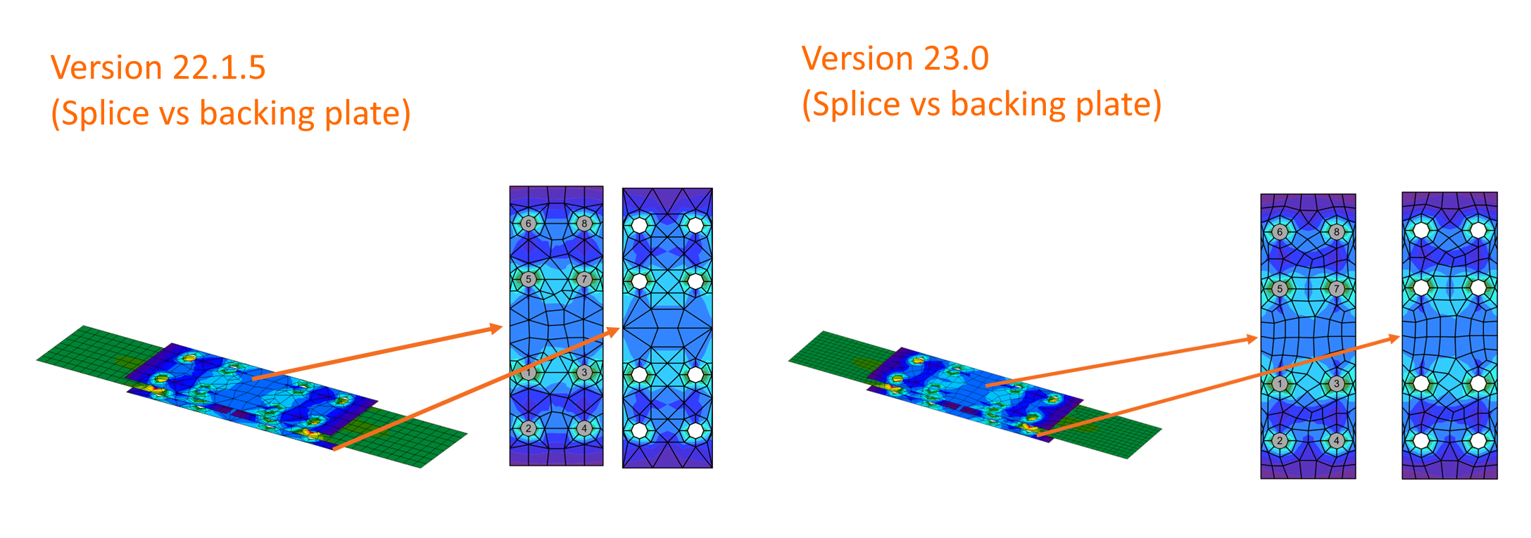
We have also programmed the newest rules for mesh generation to ensure better distribution in all plates. Connections composed of splice and backing plates, intermediate stiffening members, or stiffening plates used as custom end plates are tuned for even higher precision of analysis and match better with other parts of the connection.
Also, the default values for the mesh settings, such as the minimal size of elements and the number of elements on plates, are refined in the Code setup.

Available in both Expert and Enhanced editions of IDEA StatiCa Steel.
Download the new version of IDEA StatiCa and try all the features
Fast calculation time and redrawing of results
Our mathematical team has improved the performance of the analysis solver. According to internal tests, there is a 35% average decrease in solver run time (calculation time may vary depending on connection models and CPU configuration).
Redrawing results in the 3D scene is now faster as well. Benchmark tests on large projects in the Member app show a speed up by 20-25%. 3D scene refreshing was simplified as well, instead of clearing entities one by one, they are now cleared as a whole.
Available in both Expert and Enhanced editions of IDEA StatiCa Steel.
Download the new version of IDEA StatiCa and try all the features
Base plate extended over concrete block
In previous versions of IDEA StatiCa Connection, the whole concrete block used for anchoring a base plate used to be meshed for the analysis, meaning increasing the calculation time, especially in models with larger concrete blocks and a higher number of load effects.
This improvement ensures that only the necessary area of the concrete block is meshed and the untouched remaining surface is ignored.
This leads to cutting the calculation time dramatically for some models while the same safe and precise results are still provided.
Available in both Expert and Enhanced editions of IDEA StatiCa Steel.
Download the new version of IDEA StatiCa and try all the features
News for Concrete and Prestressing
Our Concrete improvements are of a truly practical and international nature. And for those more demanding Concrete users of you out there, you will be excited to learn that we have implemented automized calculation of equivalent time for long term deflection in the Beam application. And what about those international updates?
Although metric is commonplace in Europe, the US and Middle East markets still use imperial. Previously, in the Detail application, when you applied new entities to the model that were in metric units but presented everything in imperial units, you got dimensions containing many decimal places. Not any longer. From 23.0 onwards, the dimensions can be rounded according to your preferred unit system.
It is now also possible to run a limited stress check to ignore any irrelevant stress peaks for SLS checks of concrete, which is fully in compliance with Eurocode. You get a 100% code check with a warning about neglected parts, while still remaining completely safe. This and the other enhancements to Detail mean it is an impressive 25% faster, saving you both time and money!
Member also enjoys a serious mesh update in the form of triangular mesh. This brings the advantage of a much bigger mesh and the results being less mesh sensitive. Plus, due to the lower amount of finite elements, the calculation is faster, the presentation of the results is faster and the application’s response is better, too.
The improvements in Concrete and Prestressing include:
Limited stress check feature in Detail
Stress peaks (singularities) can be neglected from the stress limitation check! Before we explain this option in detail, let's recall how the singularity, which can be neglected, and stress concentration, which cannot be neglected, differ. In the figure below, you can see a typical stress peak (singularity) in a sharp corner and a typical stress concentration around an opening.

It looks very similar, so how can you recognize the singularity from the stress concentration? When can you use the limited stress check? Well, the fact is that the decision is always up to the responsible engineer. We can offer you advice and name some typical singularities to help you.
- When there is a rapid change in stress in one element of the mesh – there is a singularity.
- If the stress is high above the limit only in one node of the mesh – there is a singularity.
- Only the very small areas of unsatisfactory stress should be neglected.
- Typical singularities – sharp corners, the point of the mesh that is near to the anchorage or bearing plate and is not included in the partially loaded area.
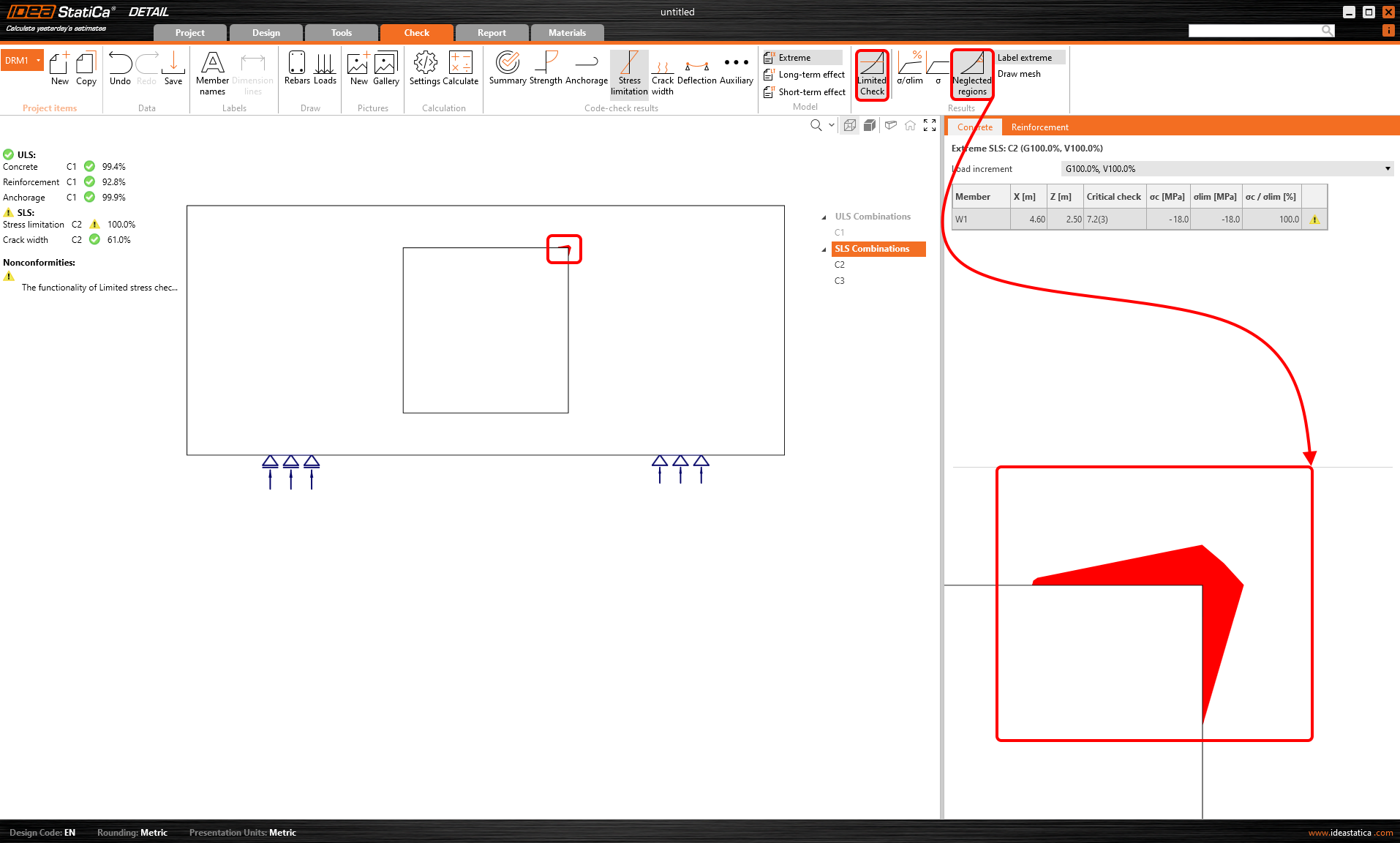
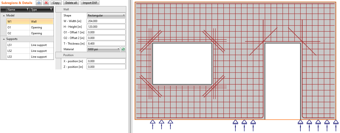
Now, let's explain how the feature works. There is a wall with an opening with an unsatisfactory stress limitation check in the right sharp corner.
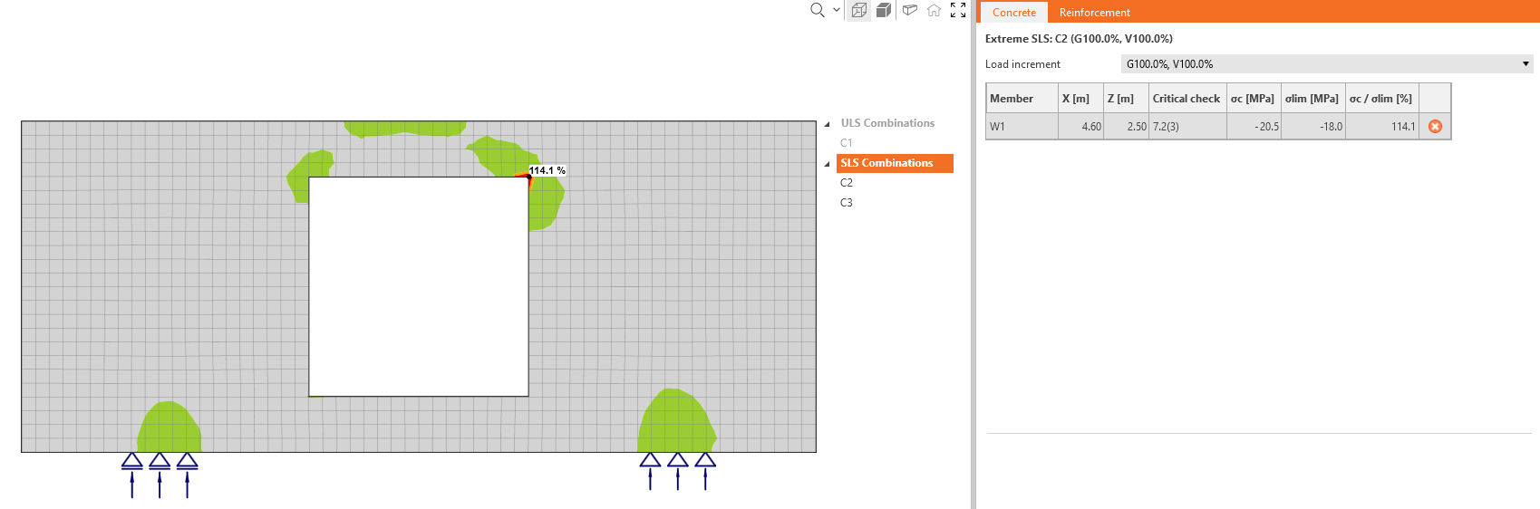
As you can see, the area is very small according to the whole structure. There is a option in the top ribbon that allows you to neglect the unsatisfactory areas.
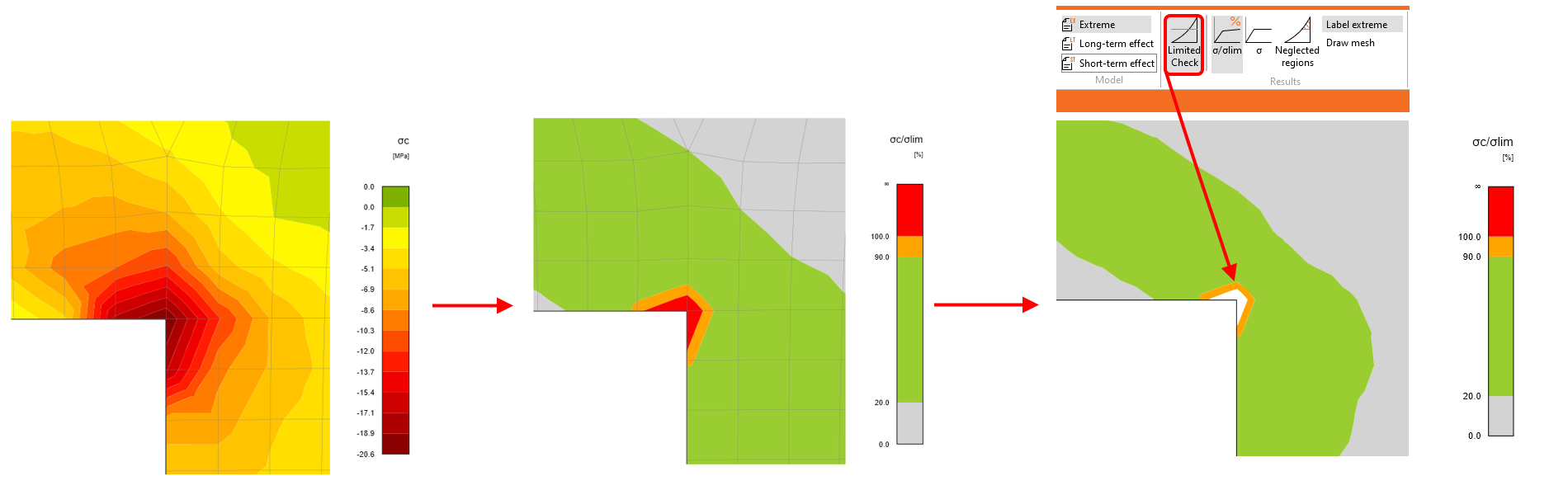
The utilization is then 100%, and nonconformity appears.

You can also display the neglected areas.
All of these checks and images can be added to the report. So it will be shown that some areas were neglected, or how large these areas are. You can choose if you want to report original values or not, etc.
Download the new version of IDEA StatiCa and try all the features
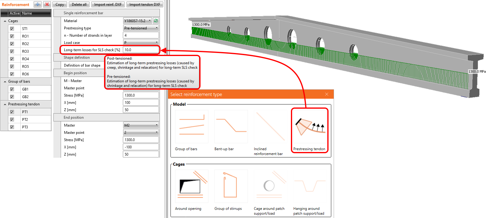
Implementation of long-term losses in Detail
From version 23.0, you can set the estimation for long-term losses for pre-tensioned and post-tensioned tendons. It means that you won't have to complicatedly create special combinations with different prestressing coefficients to assess the structure at the beginning and end of its service life. A new entity in the properties of prestressing tendon called Long-term losses for SLS check [%] is now available, which allows you to check the short-term and long-term effects within one combination.
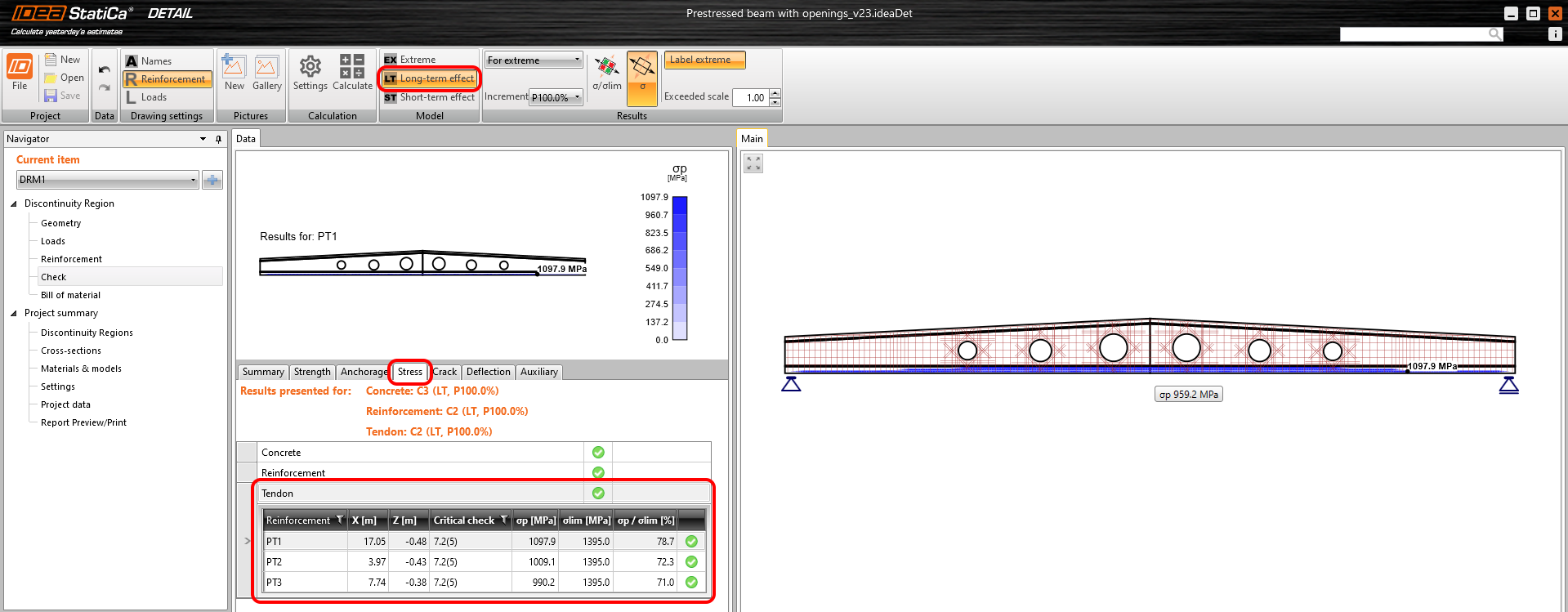
After calculation, you can switch between long-term and short-term to see the different results affected by the different material models as well as different initial stresses in the tendon.
How does it work? Read the following text to explore all the consequences of this new functionality.
For the calculation of the long-term effect in SLS checks, the values of stresses in the prestressing reinforcement are reduced by the defined value of the long-term losses. In other words, reduced stress by the estimation of long-term losses is used for prestressing increment where the Ec,eff,press is used.

The value of long-term losses for SLS check [%], which should be set for pre-tensioned and post-tensioned tendons, differs. Here's why.
Pre-tensioned tendons
For pre-tensioned tendons, the input stress is the stress just before the release from abutments (stress after short-term losses due to anchorage set -> slip, deformation of abutments, short-term relaxation, etc.). The elastic strain in concrete is automatically calculated with the corresponding material model (Ecm is used for short-term effects, and Ec,eff,press is used for long-term effects). It follows that the long-term losses for the SLS check [%] is the value defining long-term losses caused by shrinkage and long-term relaxation. The default value is 10%.
As you can see in the figure below, there are now three types of stress.
- Input stress just before the release
- Stress after short-term losses
- Stress after long-term losses
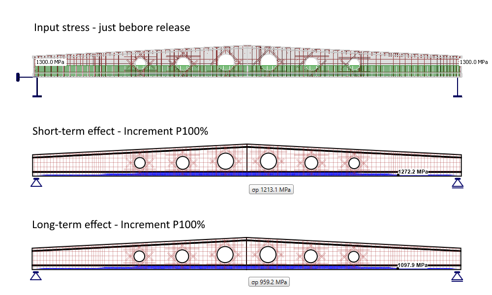
Note that the self-weight is defined as a prestressing load type. The first increment (including self-weight) prestressing is shown.
Post-tensioned tendons
For post-tensioned tendons, the input stress is the stress after short-term losses, or you can set the anchorage stress and get the program to calculate the short-term losses automatically. Short-term losses, in this case, are – friction, immediate elastic strain in concrete, and anchorage set -> slip. It follows that the long-term losses for SLS check [%] is the value defining long-term losses caused by creep, shrinkage, and long-term relaxation. The default value is 10%.
As you can see in the figure below, there are now two types of stress.
- Input stress = Stress after short-term losses
- Stress after long-term losses
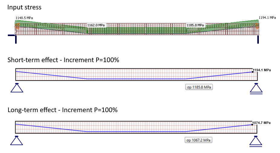
Note that the self-weight is defined as a prestressing load type. The first increment (including self-weight) prestressing is shown.
Available in Enhanced editions of IDEA StatiCa Prestressing.
Download the new version of IDEA StatiCa and try all the features
Improvements for ACI 318-19 in Detail
The application environment for users who work with ACI code was adapted to imperial units, materials defined by the code, detailing rules, code-checks, nomenclature, etc. These implemented improvements will make Detail more user-friendly and understandable for ACI users.
Let's go through the new features one by one!
New Templates for ACI code
A brand new set of templates for ACI code was created concerning the detailing rules and materials defined by ACI 318-19.
In a New project window, you can see three sets of new templates – Beams, Frame joints, and Walls.

Once you choose and select the template, the new model, including reinforcement, loads, and combinations, is created.
The proper grid for imperial units
The grid in the scene in the main graphical window is now presented correctly rounded in feet and inches if imperial units are set.
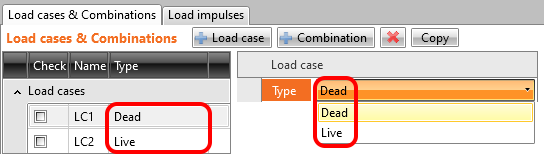
Renamed load types
Since the ACI code has different terminology, we redefined the load case types. Dead load and Live load replaced Permanent and Variable.
Anchorage type
Compared to the previous version, now, we allow defining reinforcement without any modification at the beginning (end), such as a hook, perfect bond, etc.

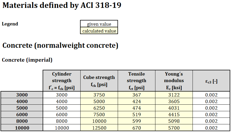
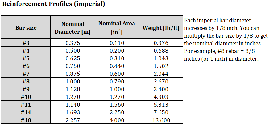
The new set of materials defined in ACI 318-19
ACI 318-19 defines materials of normal-weight concrete and reinforcement (non-prestressed deformed bars), and they are now implemented in the Detail app. The materials are defined in imperial units as well as in metric units. All material properties (for concrete and steel reinforcement) defined by ACI 318-19 (and relative ASTM docs) are specified below.

Available in Enhanced editions of IDEA StatiCa Concrete.
Download the new version of IDEA StatiCa and try all the features
Imperial rounding improvements in Detail
We distinguish two types (groups) of units:
- Units for presentation purposes
- Units for the applying of new entities into the model
These groups are independent and can be arbitrarily combined (for example, metric units for presentation but imperial units for application of the new entities).
For this purpose, the new feature that defined the type of preferred dimension for new entities was implemented. When defining a new project, the user can set if the dimension of all entities (geometry, load, reinforcement) input into the model will be rounded for metric or imperial units.

When you decide to change the setting of application units in an existing project, it can be done in Settings.

Let's also recall where you can set the presentation units. Go to File -> Units and make changes.

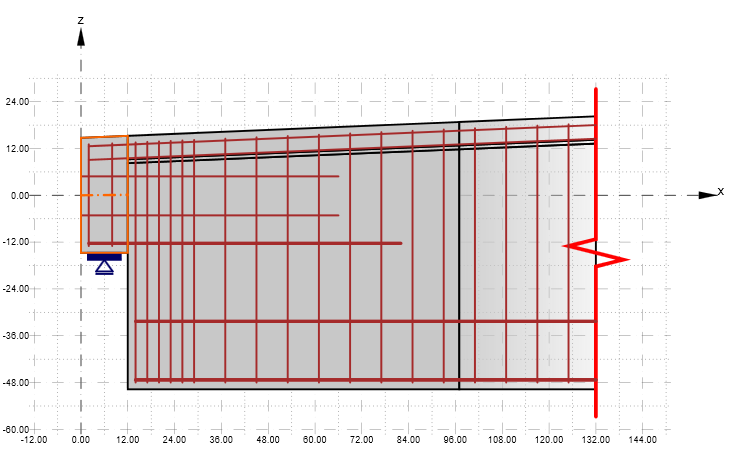
For example, an I-shaped cross-section is presented with a different combination of application and presentation units.

Available in Enhanced editions of IDEA StatiCa Concrete and Prestressing.
Download the new version of IDEA StatiCa and try all the features
Realistic reinforcement layouts in Detail
Concrete cover improvement (for ACI and EN) – when the beam element is modelled, the concrete cover for longitudinal reinforcement can be calculated considering the biggest stirrups' diameter. The reinforcement layout is also closer to reality, and longitudinal rebars do not collide with stirrups.

This option can be turned ON or OFF in Settings.

Available in Enhanced editions of IDEA StatiCa Concrete and Prestressing.
Download the new version of IDEA StatiCa and try all the features
Equivalent time for deflection evaluation
The calculation is based on a linear deflection from permanent loads (or prestressing) applied in construction stages. The calculation will be performed after clicking the Auto button (the value can still be defined manually).
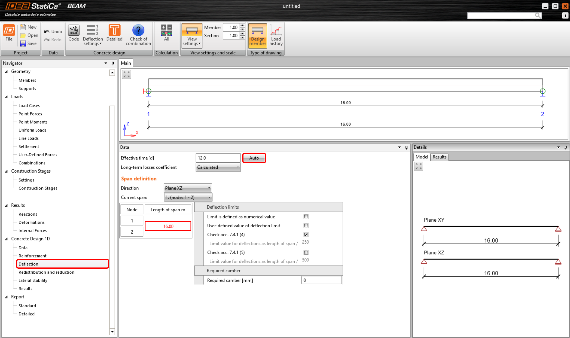
The effective time d is calculated according to the formula:
\[d = \frac{{\sum\limits_{n = 1}^i {{t_i}\cdot\,{u_{st,i}}} }}{{\sum\limits_{n = 1}^i {{u_{st,i}}} }}\]
where
ti time when the load (or prestressing) for each phase is applied
ust,i the absolute value of the maximum short-term linear deflection from the applied load (or prestressing)
The particular times used when the load is applied can be found in the construction stage tab, whereby, the superimposed dead load is the last phase taken into account. The used value of the linear deflection has been calculated by the software. For the construction stage in which we apply prestressing, we consider both values in the calculation – from the permanent load and from prestressing.
Available in both Expert and Enhanced editions of IDEA StatiCa Concrete and Prestressing.
Download the new version of IDEA StatiCa and try all the features
Triangular mesh in concrete Member
A triangular mesh for cross-sections has been implemented in the Member application for concrete members. The rectangular mesh that was used previously was sufficient for members in bending only if the very fine mesh was defined. The reason is that the results are calculated in the integration points located in the center of gravity of each finite element, so we don't calculate the actual stress at the edge of the cross-section. Results are then very sensitive to mesh size, especially for members in bending, for which the compressive zone in concrete could be just a few centimeters high. Hence, many finite elements cause a slowing down of the calculation as well as the presentation of the results in the 3D scene.
All these problems have been solved by implementing the triangular mesh for sections calculated by the MNA and GMNIA analysis. Integration points are located in nodes (finite element vertexes), so we get results at the edge of the cross-section to capture stress peaks in concrete due to bending. This brings many advantages to users. The results are not sensitive to mesh size, so by default, the mesh is rough (in comparison with rectangular mesh), leading to decreasing the calculation time and faster application response when working with results along with more precise and safer results.

Available in the Enhanced edition of IDEA StatiCa Concrete
Download the new version of IDEA StatiCa and try all the features
Minor improvements
- Faster calculation by up to 25 % in Detail (again!)
- Transition length added to SLS for pre-tensioned tendons in Detail
- GMNIA analysis in Member now includes the code-checking of shear and torsion
News for BIM links
BIM interconnectivity of IDEA StatiCa applications with the third-party software has been here for some time. The coverage of the brands and products is really wide, with thirteen in-the-house solutions and several more developed on side of our partners. So, the focus for version 23.0 was not about the number of links, but about the quality and reliability. What has been changed is the way in which we read and use data from other applications. This means our users shouldn't experience any surprises in special cases and workflows.
Our new BimApi solution is continuously spread within the BIM portfolio, and the Load mapping algorithm has got to the new generation of connection recognition.
BIM link with RFEM 6 and RSTAB 9
The list of supported third-party applications was once more extended in patch 22.1.4, enabling RFEM 6 and RSTAB 9 to be a part of the standard Checkbot workflows within the IDEA StatiCa software package.
How to activate the BIM link with RFEM 6 and RSTAB 9
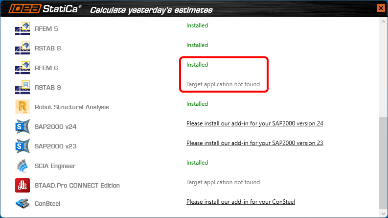
Download and install the latest version of IDEA StatiCa. Open IDEA StatiCa and navigate to the BIM tab and open the BIM link installer (Activate your BIM link...).

A notification "Do you want to allow this app to make changes to your device?" may appear. If so, please confirm with the Yes button.
The BIM link for RFEM 6/RSTAB 9 is installed. The screen also tells you the status of other BIM links that are installed or may be installed later.
Open RFEM 6/RSTAB 9 and navigate to the menu Options and Program options. Here, scroll down and turn on the WebService feature to enable the data transfer of your RFEM 6/RSTAB 9 and other applications.

How to use Checkbot with RFEM 6 and RSTAB 9
Open an RFEM 6/RSTAB 9 project and run the calculation. To run the Checkbot, open the shortcut icon IdeaRFEMLink/IdeaRSTABLink, by default, located on your desktop (original file in path C:\Program Files\IDEA StatiCa\StatiCa 22.1\net6.0\IdeaRFEMLink.exe).

Checkbot for the current RFEM 6/RSTAB 9 project opens, and you can create a new project and start importing connections and members.
Limitations
- Missing a command directly in the application RFEM 6/RSTAB 9 instead of a desktop shortcut icon.
Waiting for Dlubal development to add the commands in their menu/interface. - Result combinations are not supported.
Waiting for Dlubal development to provide the necessary data provided in the API.

- Eccentricities specified relatively in RFEM 6/RSTAB 9 are not supported. Only absolute eccentricities can be imported.

Available in both Expert and Enhanced editions of IDEA StatiCa Steel.
Download the new version of IDEA StatiCa and try all the features
Unified BimApi solution – Advance Steel, SAP2000, ETABS
We have developed a unified BimApi solution for faster integration and better cross-section recognition.
This affects other third-party software and covers, namely, Advance Steel, SAP2000, and ETABS.
It can also deal with eccentricities, concrete cross-sections and materials.
Note: Older projects can be opened but not updated (the member links are broken)
Available in both Expert and Enhanced editions of IDEA StatiCa Steel.
Download the new version of IDEA StatiCa and try all the features
Load mapping algorithm for importing steel connections
This helps mostly in cases with this typical workflow. The connection designer wants to load the structural model of a connection from a detailer (exported from CAD) using loads in a model provided by an engineer (exported from FEA). This workflow saves a lot of time and provides effective use of the data exchange between offices and applications.
Fewer limitations:
- LCSs of the current model and the model being imported don't have to be identical
- The order in the project member list doesn't need to be the same
The algorithm automatically recognizes and identifies the corresponding members and reliably assigns the load effects to them.
Available in both Expert and Enhanced editions of IDEA StatiCa Steel.
Download the new version of IDEA StatiCa and try all the features
Selezione del carico estremo
La funzione è stata rilasciata nella patch 22.1.3 e aggiornata nella 23.0.1.
I progettisti di connessioni in acciaio hanno bisogno di iterare per arrivare rapidamente il progetto finale. Per farlo, non è necessario valutare l'intera serie di effetti di carico sul modello. È sufficiente utilizzare gli effetti di carico critici per ottenere questo risultato.
Nel caso di dettagli complessi, si consiglia di eseguire l'analisi finale con l'intero set di effetti di carico, in modo da coprire tutti i carichi definiti dal progettista.
Esistono diversi modi per definire gli effetti di carico nel modello IDEA StatiCa Connection. Per diversi effetti di carico, il modo più semplice è importare i carichi tramite un collegamento BIM o utilizzare l'opzione di Importa XLS.
È anche possibile ricevere gli input di carico in un foglio Excel, che può contenere centinaia di combinazioni di carico per ogni connessione. Poiché è molto inefficace calcolare una tale quantità di effetti di carico (in termini di tempo) in IDEA StatiCa Connection, è necessario selezionare solo quelli decisivi, riducendo così il numero totale di effetti di carico (e il tempo!).
IDEA StatiCa Connection dispone ora di un'utile funzione per filtrare gli effetti di carico estremi in modo automatico e semplice. Ma prima...
Qual è il carico estremo?
La selezione del carico estremo valuta le componenti di carico di ogni membratura collegata nella connessione e seleziona quelle più estreme in base ai seguenti criteri:
- Massimo positivo o negativo di ogni componente di carico (N, Vy, Vz, Mx, My, Mz) - 12x
- Massima risultante della forza di taglio - 1x
- Massima risultante del momento flettente - 1x
- Massima risultante normale positiva e negativa - 2x
- Massima risultante di taglio - 1x
- Massima risultante totale - 1x
- Sollecitazione massima al bordo della sezione trasversale - 2x
È possibile selezionare un massimo teorico di 20 estremi di carico per ogni elemento collegato. Il numero totale di estremi selezionati è quindi n x 20, dove n è il numero di elementi di una connessione. Tuttavia, il numero di set di carico selezionati può essere inferiore, poiché gli estremi degli elementi si sovrappongono.
Vediamo ora come filtrare i valori estremi.
Selezionare gli estremi ed eseguire l'analisi
Per selezionare gli estremi da analizzare, utilizzare il tasto destro del mouse sugli effetti di carico e selezionare l'opzione Calcola carichi estremi.
In questo modo vengono deselezionati dall'elenco gli effetti di carico non rilevanti (non estremi). Il motivo di ogni effetto di carico estremo selezionato è presentato nella descrizione sotto la tabella.
Importazione degli estremi da XLS
È possibile utilizzare la selezione degli estremi anche quando si importano i valori di carico da un foglio Excel. Selezionare la casella Importa solo gli estremi. Viene immediatamente visualizzato il numero di effetti di carico considerati estremi.
Gli effetti di carico estremi vengono importati e gli altri vengono ignorati.
Impostazione delle tolleranze
Per trascurare i valori irrilevanti (piccoli) degli estremi, è possibile impostare i limiti/tolleranze per ogni componente delle forze interne. Il valore della forza (un valore assoluto) inferiore al limite impostato non verrà considerato per valutare gli estremi.
Quando si modificano questi valori in valori più elevati, vengono presentati un avviso e i motivi per cui è stato selezionato l'effetto del carico.
È possibile salvare i valori personalizzati tra i modelli e utilizzarli in un altro progetto caricandolo o impostando il modello come predefinito.
Selezione di carichi estremi tramite Checkbot (collegamento BIM)
Esiste anche un'altra possibilità per filtrare i carichi estremi nel caso in cui si utilizzi il collegamento BIM (IDEA StatiCa Checkbot). Aprire il configuratore di carico in Checkbot e andare su Classi di risultato per le verifiche nella colonna centrale. Selezionare la classe di risultati desiderata e, nel campo a destra, specificare se i carichi devono essere filtrati. Quando è selezionata la casella di controllo Valutare gli effetti critici, gli estremi della forza vengono filtrati. È necessario Aggiornare il carico dopo aver chiuso la finestra del configuratore di carico.
Si noti che l'algoritmo di filtraggio differisce dalla procedura sopra descritta: Per saperne di più, consultare l'articolo Valutare gli effetti critici per i carichi importati tramite collegamenti BIM.
Disponibile nelle edizioni Expert e Enhanced di IDEA StatiCa Steel.
Scarica la nuova versione di IDEA StatiCa e prova tutte le funzionalità
Setting up parametric design with Developer Tab
It is not necessary to manually modify the IdeaConnection.exe.config file in the root folder, which would be time-consuming and inconvenient.
Thanks to the raising numbers of advanced users of IDEA tools, it is enough to just enable the Developer mode in Project tab/Preferences.

This brings the user a new tab in the main toolbar, with additional features.

Export IOM:
- Model – export the model data through IOM (Idea Open Model) in .xml format
- Conn Data – export the model data through IOM in .json format
Template:
- Save as – the user can save the connection model properties in the Idea Template (.IdeaTemp) format
- Apply – the user can apply Idea Template format to the whole Connection model (all members are involved)
- Simple – the user can apply Idea Template format to a selected part of the Connection model (only selected members are involved)
There is also a property grid window part-displayed with two separate tables:

Parameters table – this provides the user with the set of IOM parameters that are available to use for parametric design
Model parameters – this allows joining the specific IOM parameter with the specific Model parameter of the current Connection project
Other improvements are described in the UX Improvements of Parametric design article.
For more information about these features, please visit our GitHub page
https://github.com/idea-statica/ideastatica-public/wiki/Developer-Mode-Parameters#parameter-input
https://github.com/idea-statica/ideastatica-public/wiki/Reference-Guide-Expression-Parameters
This feature can be found in the applications Connection and Member.
Available in both Expert and Enhanced editions of IDEA StatiCa Steel.
Download the new version of IDEA StatiCa and try all the features
If you want to check the compatibility with your particular application, just take a look at our list of actively supported versions in 23.0.
Cloud & Licensing & All applications
The biggest news in the Cloud is that Web Connection Browser has been renamed Connection Library. This was the decision after a lot of market research into how we can make the library more user-friendly, intuitive and optimize its workflow.
User Portal has also been improved to report the product version, country analytics, the reporting of license clashes and the licensing system has increased stability, eliminating any related support cases.
Connection Browser renamed Connection Library
The Connection Library functionality will not be touched by this change, it still uses the Cloud-based technology and provides design templates to be directly used for new projects, saved in the database from current projects, and shared with your colleagues.
The design sets will be slightly renamed as well following this pattern:
- Predefined (before IDEA StatiCa) – the default design set maintained by IDEA StatiCa, not possible to manage.
- Personal (before Private) – a design set visible only to the current user, possible to add/delete/manage templates.
- Company (before Company) – a design set visible only to all users of the same license, possible to add/delete/manage templates.
Available in both Expert and Enhanced editions of IDEA StatiCa Steel.
Download the new version of IDEA StatiCa and try all the features
User Portal – last time active, version tracking
One of the main purposes of the User Portal is to see clearly where and when potential issues with the license are happening on the user side. Also, to provide users and admins more control over the license and usage of the application.
You can find the following data in the section License & Users in the User Portal:
All users, including admins
- Last time active
- User setting of the tickbox Keep products reserved
- Used version
Admins only
- More information about usages and clashes – An admin is able to see the details of license clashes, especially the daily instances of clashes and also the users who were colliding.
We have also implemented measures (such as the proper release of licenses) to reduce clashing and licensing issues.
Available for all editions of IDEA StatiCa.
Download the new version of IDEA StatiCa and try all the features
RELATED ARTICLES
Piano IDEA StatiCa Basic
Per creare un account e accedere al Portale Utente IDEA StatiCa non è necessaria una licenza valida a pagamento. Ciò consente a tutti gli abbonati di usufruire di quanto segue:
- Checkbot gratuito
- Viewer
- Connection Library
- Campus E-learning
Uno dei principali vantaggi di questa opzione è quello di velocizzare la comunicazione tra gli utenti interessati e IDEA StatiCa senza la necessità di richiedere una licenza quando si utilizzano solo il Checkbot Gratutio, gli strumenti Cloud e l'E-learning.
Per creare un account Basic, fare clic sull'icona della licenza Portale Utente nella barra dei menu in alto del nostro sito web.

Fare clic su "Non hai ancora un account? Crea il tuo account IDEA StatiCa" e completare il modulo nella pagina successiva.

Una volta ricevute le credenziali nell'e-mail, scaricare l'ultima versione di IDEA StatiCa da qui, attendere che il file completi il download. A questo punto è possibile fare doppio clic sul pacchetto di installazione nella cartella dei download e procedere all'installazione utilizzando la procedura guidata passo-passo, inserendo le proprie credenziali quando richiesto.
Solved incidents
See the current list of solved incidents reported by our customers.